Control Architectures
Overview
This section details the primary system architectures compatible with LightForce, including common configurations and integration guidelines to support practical implementation.
| Architecture | Configuration | Description |
|---|---|---|
| Direct Control | Human-in-the-Loop Direct Control | LightForce directly commands actuators or subsystems based on physical or RF human input devices. |
| Direct Control | RC-Integrated Control | LightForce receives remote control inputs and executes real-time platform control with optional telemetry return. |
| Remote & Supervisory Control | Ground Node + Transmitter | A ground-deployed LightForce communicates with one or more remote platforms over RF or network links. |
| Remote & Supervisory Control | Companion Computer Model | LightForce performs deterministic real-time control while an external processor manages mission-level logic or perception. |
| Remote & Supervisory Control | Telemetry Relay Model | LightForce streams system state data to external systems while accepting high-level supervisory commands. |
| Distributed Control | Functional Partitioning (Dual Node) | Multiple LightForce units control separate subsystems within a single platform and may cross-monitor each other. |
| Distributed Control | Subsystem Segmentation | Dedicated LightForce units independently manage propulsion, sensing, manipulation, or payload subsystems. |
| Redundant & Fault-Tolerant Control | Dual-Redundant Architecture | Primary and secondary LightForce units provide monitored failover capability. |
| Redundant & Fault-Tolerant Control | Triplex Voting Architecture | Three LightForce units implement majority-vote logic to enhance fault tolerance and system integrity. |
| Hybrid Ground-Remote Control | RF Link Extension Architecture | A ground LightForce extends or relays communications to increase operational range or coverage. |
| Hybrid Ground-Remote Control | Distributed Command Hierarchy | Ground and remote LightForce units operate in supervisory–execution roles within a hierarchical control structure. |
| Multi-System and Networked Control | Synchronized Multi-Apparatus Control | Multiple LightForce-controlled systems operate under shared timing and coordinated command execution. |
| Multi-System and Networked Control | Swarm or Mesh Architecture | Multiple LightForce nodes operate in peer-to-peer or coordinated network topologies for distributed operation. |
| Multi-System and Networked Control | Infrastructure-Control Node | LightForce controls stationary or support apparatus synchronized with mobile platforms. |
Direct Control Architectures
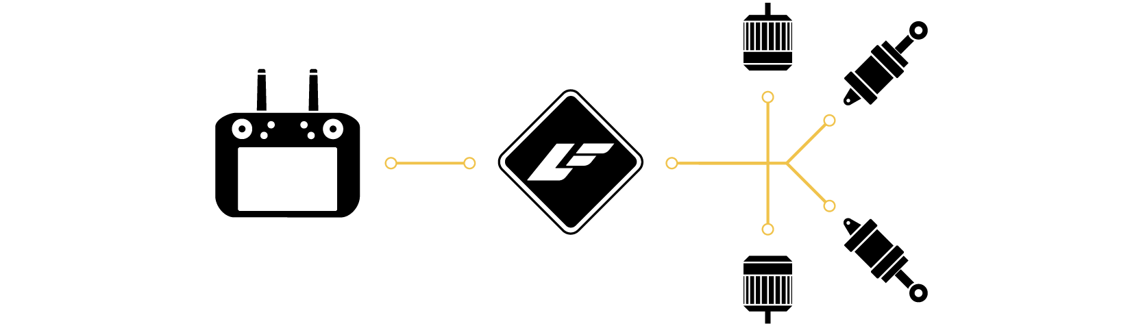
Direct control architectures position LightForce as the primary real-time control node between human input devices and actuator subsystems. In these configurations, LightForce executes deterministic control loops with minimal external dependency.
| Operational Characteristics | Typical Use Cases | Integration Considerations |
|---|---|---|
|
|
|
Human-in-the-Loop Direct Control
In this configuration, LightForce operates as a real-time control intermediary between a human input device and one or more actuator subsystems. Physical or RF inputs are translated into deterministic control outputs with bounded latency and configurable safety constraints. This architecture is well suited for manual operation, subsystem testing, and applications where direct operator authority is required while maintaining embedded stabilization and safeguard logic.
Example: Controlling a robotic arm with direct joystick input
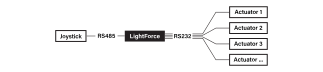 In this example, a locally connected joystick provides real-time input via RS485 to LightForce, which directly commands a robotic arm or actuator subsystem via RS232. LightForce performs signal conditioning, constraint enforcement, and closed-loop control to ensure stable and bounded motion execution.
RC-Integrated Control
The RC-Integrated Control configuration enables LightForce to receive commands via a remote control link and execute closed-loop control directly on the platform. Telemetry may be transmitted back to the operator or auxiliary systems, allowing situational awareness without offloading real-time control responsibilities. This architecture preserves low-latency responsiveness while supporting remote operation over RF or networked interfaces.
Example: Controlling a generic vehicle or robotic platform via RC transmitter
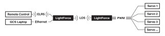 Here, LightForce receives commands via an RF transmitter over an ELRS link and executes deterministic control on a LightForce-controlled remote platform via a LOS link. An auxiliary laptop may optionally receive telemetry or issue high-level commands without interfering with real-time control authority.
Supervisory Control Architectures
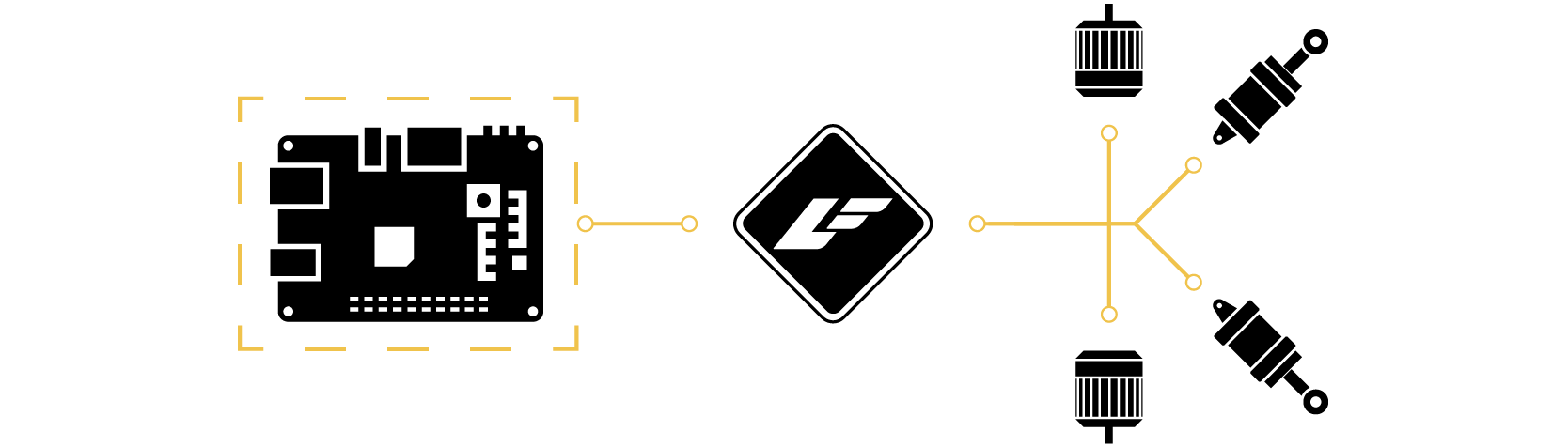
Supervisory and remote control architectures enable LightForce to operate within systems where command authority or mission logic resides off-platform. LightForce maintains real-time control while interfacing with remote operators or higher-level computing systems.
| Operational Characteristics | Typical Use Cases | Integration Considerations |
|---|---|---|
|
|
|
Ground Node + Transmitter
In this architecture, a ground-deployed LightForce unit interfaces with one or more remote platforms through RF or network links, serving as a centralized command and telemetry hub. The ground node may aggregate operator inputs, manage communication routing, and coordinate multiple remote systems. This configuration supports structured command hierarchies and scalable multi-platform deployments.
Example: Controlling multiple systems from a stationary LightForce and RC transmitter
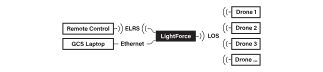 A stationary LightForce interfaces with an RC transmitter and manages communication with one or more remote platforms. The ground node may aggregate telemetry, route commands, and coordinate multiple vehicles under a unified operational framework.
Companion Computer Model
The Companion Computer Model separates real-time deterministic control from higher-level computational tasks. LightForce maintains authority over stabilization, state estimation, and actuator control, while an external processor executes mission logic, perception algorithms, or AI workloads. This architecture allows computational scaling without compromising real-time performance or safety boundaries.
Telemetry Relay Model
Under the Telemetry Relay Model, LightForce provides continuous state and health data to external systems while accepting high-level supervisory commands. Real-time control loops remain onboard, while off-platform systems monitor performance, issue mode changes, or adjust operational parameters. This configuration is effective where centralized oversight is required without relinquishing embedded control autonomy.
Example: LightForce with link to cloud services
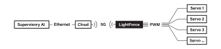 A LightForce may interface with external networks via 5G/6G or satellite links to exchange telemetry and command data with cloud-based analytics, AI services, or supervisory systems. Real-time control remains local, while remote services provide higher-level optimization, monitoring, or decision support.
Distributed Control Architectures
Distributed control architectures deploy multiple LightForce units within a single system, partitioning responsibility across functional subsystems. This modular approach improves scalability, isolation, and performance specialization.
| Operational Characteristics | Typical Use Cases | Integration Considerations |
|---|---|---|
|
|
|
Functional Partitioning (Dual Node)
Functional Partitioning distributes control responsibilities across multiple LightForce units within a single platform. Each node governs a defined subsystem—such as mobility, manipulation, or sensing—while optionally exchanging state data for coordination. This architecture improves modularity, simplifies subsystem isolation, and allows computational and fault domains to be clearly separated.
Example: Controlling different parts of a platform with multiple LightForces
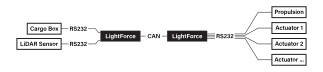 Multiple LightForce units are deployed within a single platform to control separate subsystems or to implement redundant voting logic. Nodes may operate in functional partitioning (e.g., dual control domains) or triplex configurations to enhance modularity and fault tolerance.
Subsystem Segmentation
Subsystem Segmentation assigns dedicated LightForce units to independent functional domains, enabling parallel control of propulsion clusters, sensor arrays, or payload mechanisms. Nodes operate semi-autonomously while maintaining synchronized timing or state awareness as required. This approach enhances scalability and allows targeted optimization of processing resources and interface configurations.
Fault-Tolerant Control Architectures
Fault-tolerant and redundant control architectures employ multiple LightForce units to enhance system reliability and operational integrity. These configurations support failover strategies, cross-monitoring, and voting mechanisms.
| Operational Characteristics | Typical Use Cases | Integration Considerations |
|---|---|---|
|
|
|
Dual-Redundant Architecture
The Dual-Redundant Architecture employs two LightForce units configured for primary and secondary roles. The secondary node continuously monitors system state and is capable of assuming control if the primary node fails or deviates beyond defined thresholds. This configuration enhances operational continuity and supports high-availability deployments.
Triplex Voting Architecture
In the Triplex Voting Architecture, three LightForce units operate in parallel, each independently processing inputs and generating control outputs to be shared via cross-lane datalink. A majority-voting mechanism determines authoritative commands, enabling detection and isolation of faulty behavior. This configuration provides elevated fault tolerance and is suitable for systems requiring strong integrity assurance.
Hybrid Control Architectures

Hybrid control architectures combine ground-deployed and remote LightForce nodes to extend communications, establish hierarchical command structures, or support distributed coordination.
| Operational Characteristics | Typical Use Cases | Integration Considerations |
|---|---|---|
|
|
|
RF Link Extension Architecture
The RF Link Extension Architecture utilizes a ground or intermediary LightForce node to relay or extend communication between operators and remote systems. By acting as a bridge or repeater, the intermediate node increases operational range or improves signal reliability. This configuration supports distributed deployments in environments where direct communication may be constrained.
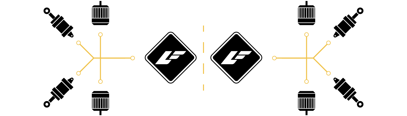
Example: Stationary LightForce in a dual-node architecture for RF link expansion
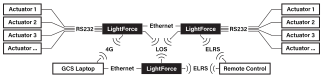 A ground LightForce operates in coordination with dual LightForce nodes onboard a platform, enabling extended communication range and distributed authority management. This configuration supports both link redundancy and partitioned control responsibilities.
Distributed Command Hierarchy
In the Distributed Command Hierarchy model, multiple LightForce units operate within a structured authority framework. A supervisory node issues high-level directives, while subordinate nodes execute deterministic control within defined boundaries. This hierarchical structure enables scalable coordination while maintaining local autonomy at the execution layer.
Multi-System Control Architectures

Multi-system and networked control architectures enable coordinated operation across multiple independent systems or apparatus. LightForce nodes share timing, state, and command data to achieve synchronized or distributed behaviors.
| Operational Characteristics | Typical Use Cases | Integration Considerations |
|---|---|---|
|
|
|
Synchronized Multi-Apparatus Control
Synchronized Multi-Apparatus Control enables coordinated operation between multiple LightForce-controlled systems, such as mobile platforms and stationary apparatus. Shared timing references and synchronized command execution allow precise coordination across independent subsystems. This configuration supports applications requiring tightly coupled motion, load management, or cooperative task execution.
Example: Synchronized heterogeneous systems
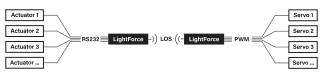 A stationary LightForce controls a stationary apparatus (e.g., winch or deployment mechanism) while coordinating timing and command execution with a mobile system. Shared state and synchronized control enable precise interaction between independent subsystems.
Swarm or Mesh Architecture
In the Swarm or Mesh Architecture, multiple LightForce nodes operate in a peer-to-peer or distributed network topology. Nodes exchange state data and coordinate behaviors without reliance on a single centralized authority. This architecture supports scalable multi-system deployments, distributed sensing, and collaborative task execution across dynamic networks.
Infrastructure-Control Node
The Infrastructure-Control Node configuration positions LightForce as the control authority for stationary or support apparatus such as winches, docking systems, or mechanical handling equipment. These systems may operate independently or in synchronization with mobile platforms. This architecture expands LightForce’s role beyond vehicle control into integrated system coordination.