LightForce Nano
Introduction
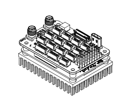
LightForce Nano is designed to provide the foundational control and processing features of the LightForce platform. This model consolidates essential system components into a compact footprint for direct integration into third-party hardware. It provides localized processing for critical system tasks, only the essential standardized communication interfaces for peripheral connectivity, and direct access to the platform’s primary logic controllers. This model is intended for applications prioritizing ease of implementation.
System Features
Feature Table
| Feature | Standard Configuration |
|---|---|
| Mission Processor | 4x Cortex-A76 at 2.5GHz |
| I/O Processor | 2x Cortex-M33 at 150MHz |
| Embedded GPU | VideoCore VII at 800 MHz |
| Storage | 32GB eMMC |
| Internal Sensors | IMU Magnetometer Dual Antenna RTK GNSS |
| Communications | Wifi Bluetooth |
| Buses | 1x 4-lane MIPI CSI 1x 100Mbps Ethernet 1x USB2 OTG at 480Mbps 1x USB2 at 480Mbps 8x PWM 2x I2C 1x CAN FD at 8Mbps 6x UART 4x RS485 9x GPIO 4x ADC |
The performance and functionality of LightForce is enhanced through optional hardware modules and software modules. See the Modularity section for more information.
Modularity
The LightForce architecture is built on a foundation of versatile, interoperable modules designed to provide high-performance autonomy across diverse operational environments. By decoupling core flight intelligence from hardware-specific sensing and control, the system offers a scalable "plug-and-play" framework. Whether deployed on a single vehicle or integrated into a complex System of Systems (SoS), these capabilities can be tailored to meet specific mission requirements, ensuring maximum reliability and tactical flexibility.
Intelligence
- Detect & Avoid
- Smart Health Monitoring
- Dynamic Path Planning
- Swarming
Navigation
- Dead Reckoning
- Vision-based guidance
- GNSS Spoof/Jam Detection
Advanced Control
- Adaptive
- Non-linear
- Tethered
External Sensors
- Lidar
- Airdata (Multi-hole Pitot)
- Fibre Optic Gyroscope IMU
- Visual / Thermal Camera
Safety
- Flight Termination (FTS)
- ADS-B / Remote ID
- Triple Redundant Voting
- Geofencing
Communication
- SATCOM
- Fibre Optics
- MAVLink
Actuators & Motors
- Servo
- Stepper
- BLDC
- +
Ground Support
- Ground Control Station
- SIL / HIL
- Mission Planning
Platforms
- UAV / USV / UGV
- Hybrid Robotic Systems
- Coordinated Swarms
- Systems of Systems (SoS)
Technical Specifications
Mechanical Specifications
The LightForce Nano is engineered with a weight-optimized mechanical architecture suitable for integration into a wide range of unmanned and autonomous platforms. Its compact form factor, reinforced mounting interfaces, and vibration-tolerant construction enable reliable operation in demanding mobile environments, while maintaining compatibility with typical structural configurations.
Dimensions
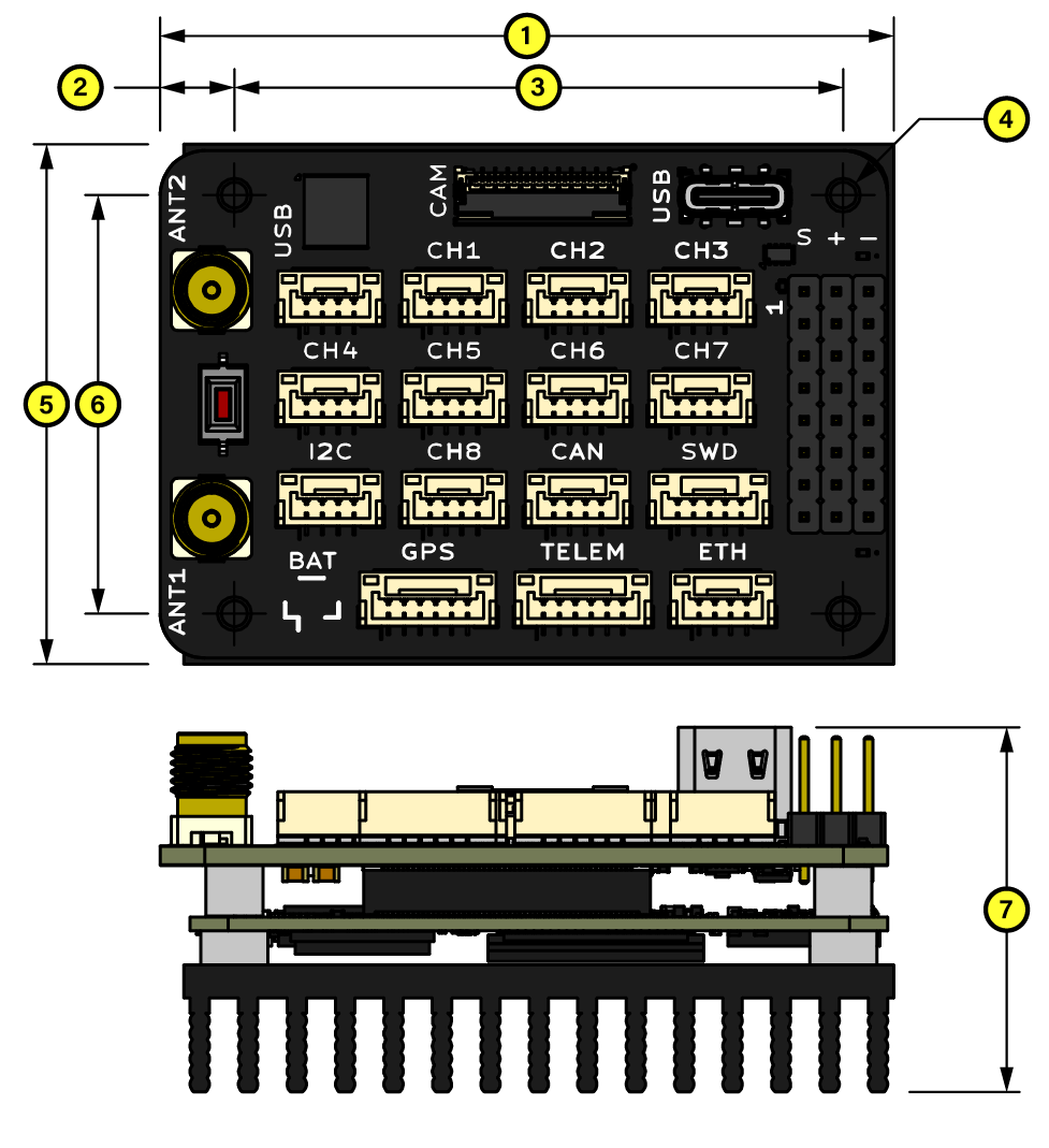
The following diagram provides an overview of the hardware's physical dimensions to assist with system integration. Key measurements are indicated to ensure proper alignment with external mounting points and connectors.
Dimensions
| Label No. | Dimension |
|---|---|
| 1 | 57.85 mm |
| 2 | 5.85 mm |
| 3 | 48.00 mm |
| 4 | 2.70 mm |
| 5 | 41.00 mm |
| 6 | 33.00 mm |
| 7 | 28.74 mm |
Orientation
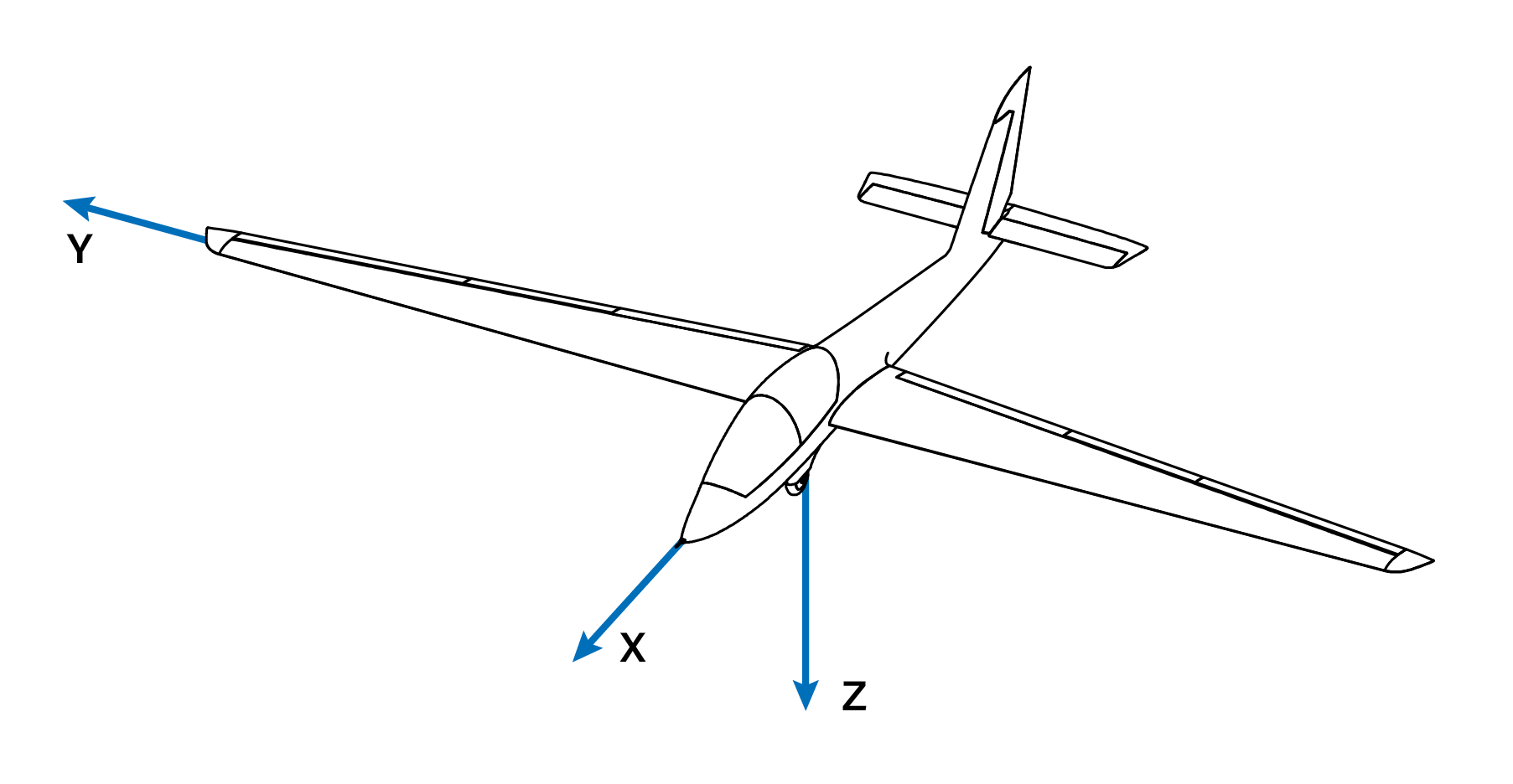
LightForce offers full mounting flexibility regardless of spatial orientation. Software-based alignment to the airframe is managed through the configuration settings, supporting both rotation matrix inputs and direct axis-mapping.
Orientation
Axes are indicated on the LightForce enclosure. For reference, the coordinate system is shown in the image at right.
Position
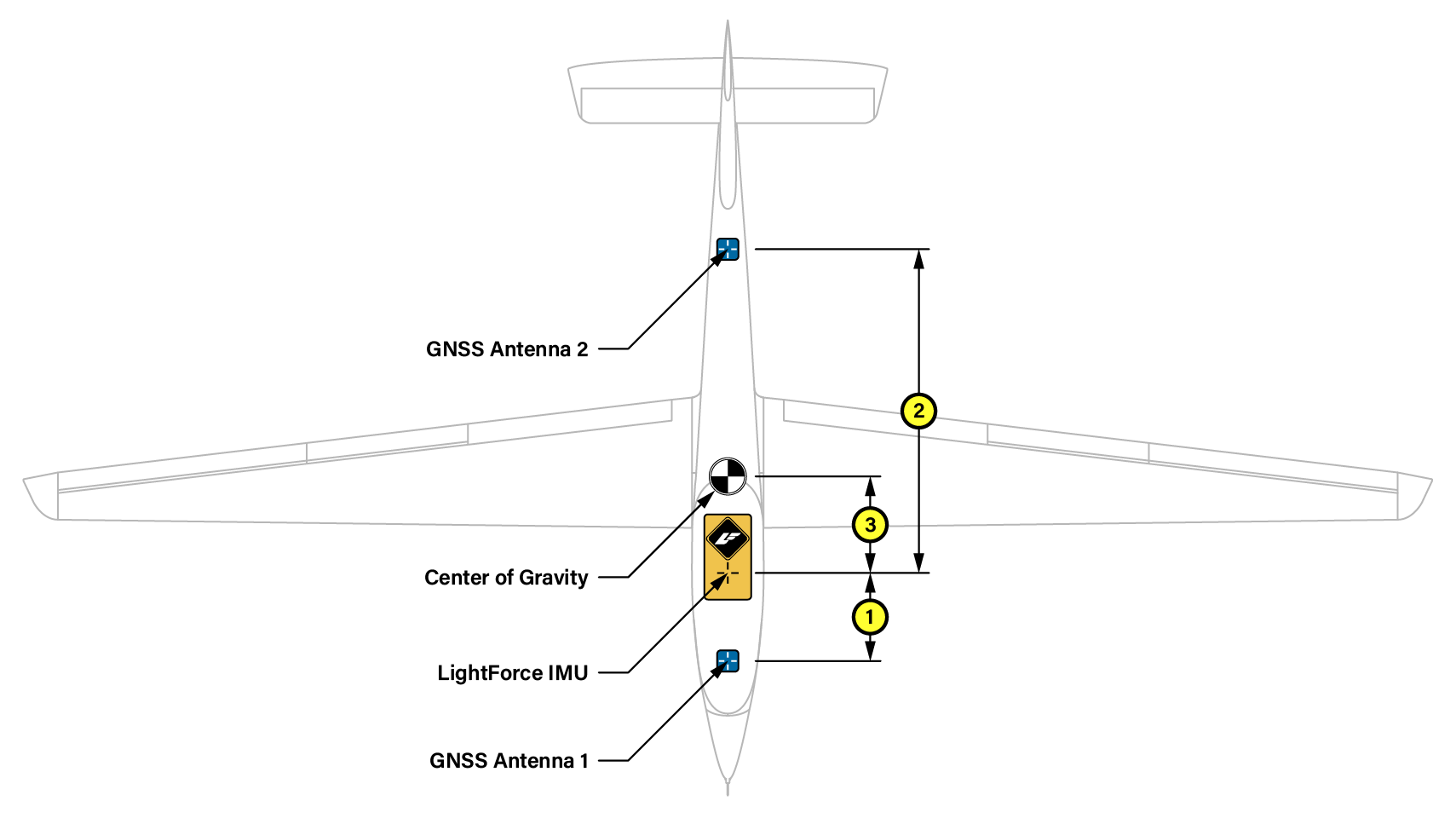
To ensure accuracy when using traditional navigation, the physical spatial relationship between the LightForce IMU and the vehicle's key reference points must be established. This is achieved by inputting the position vectors within the configuration interface.
Spatial Offset Configuration Provide two distinct sets of vector inputs:
- Dual-Antenna Baseline: Define the relative position of the two GNSS antennas with respect to the LightForce IMU center. These vectors allow the system to calculate precise heading and multi-antenna positioning.
- Center of Gravity (CG) Alignment: Define the vector from the LightForce IMU to the vehicle’s Center of Gravity, including the relative orientation expressed with Euler angles (i.e. roll, pitch, and yaw). Accurately mapping this offset is critical for the IMU to correctly compensate for centrifugal forces and rotations during high-dynamic maneuvers.
All coordinates should be entered in accordance with the primary coordinate system (typically Forward-Right-Down or X-Y-Z), ensuring that the translated data reflects the true physical displacement of the hardware relative to the airframe.
Position
| Label No. | Description | Input |
|---|---|---|
| 1 | ANT1_OFFSET | X, Y, Z |
| 2 | ANT2_OFFSET | X, Y, Z |
| 3 | IMU_OFFSET | X, Y, Z, ψ, θ, φ |
Mechanical Installation
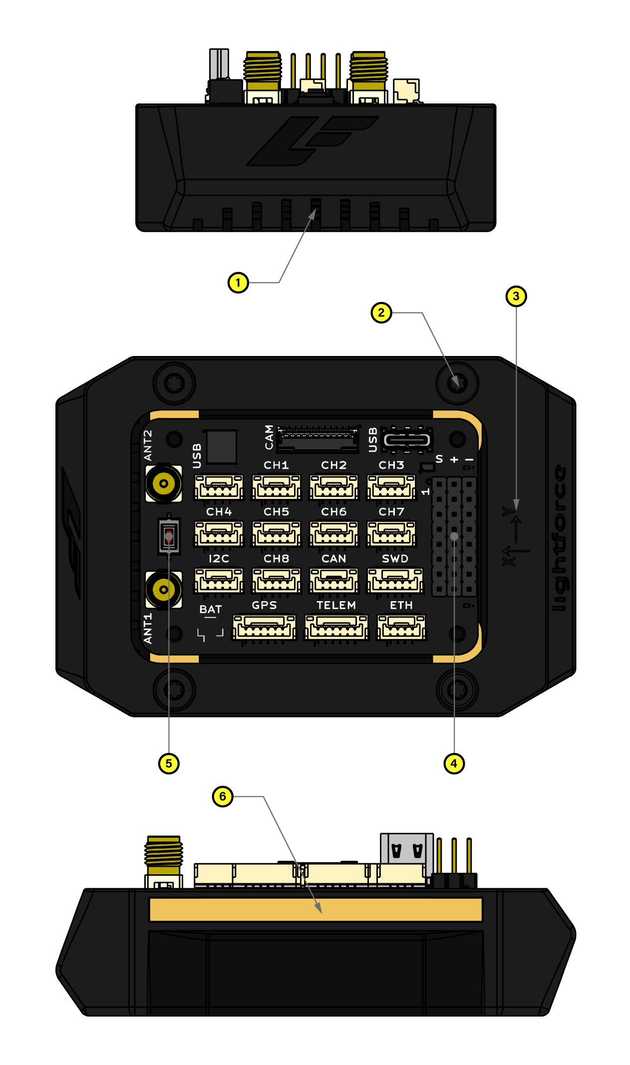
Successful deployment of the LightForce system depends on secure mounting within your vehicle or system. LightForce Nano is optionally delivered with a basic, non-ruggedized enclosure for everyday handling protection which is appropriate for benchtop testing, drive tests, and operations in optimal environmental conditions. For more information about the interfaces, consult the Interfaces section.
Basic Enclosure
| Label No. | Interface | Description |
|---|---|---|
| 1 | DUCT | Air inlets on each side of the Nano provide cool, and are best left unobstructed |
| 2 | MOUNT | Four holes are provided for mounting Nano to your vehicle frame with M2.5 hardware |
| 3 | AXES | Configured orientation axes of LightForce |
| 4 | IOB | Board interface connectors |
| 5 | BOOT | Used to enter Bootloader Mode |
| 6 | ISO | Mechanical vibration isolation |
Electrical Specifications
The LightForce Nano is designed to operate within a standard industrial temperature range and provides a versatile I/O architecture compatible with modern UAV peripherals.
| Parameter | Min | Typ | Max | Unit |
|---|---|---|---|---|
| Operational Temperature | -40 | — | +85 | °C |
| Logic Level (High) | 2.3 | 3.3 | 3.6 | V |
| Logic Level (Low) | -0.3 | 0 | 0.8 | V |
| PWM Output Frequency | 50 | 400 | 2000 | Hz |
| ADC Resolution | — | 12 | — | Bits |
| Input Voltage (VBUS) | 5.0 | — | 32.0 | V |
| Total Power Consumption | — | 3.0 | — | W |
| I/O Current Drive (Per Pin) | — | — | 15 | mA |
| ESD Protection (Human Body Model) | — | TBD | — | kV |
| Shock Tolerance | — | — | TBD | g |
Power
The LightForce Nano architecture is engineered for high-availability missions, utilizing isolated regulation domains to ensure that peripheral faults do not compromise flight-critical logic.
Primary Power Input (BUSA & BUSB)
The system is powered via the servo or the USB-C connectors.
- VBUS: 5V-32V (Supports 2s to 7s LiPo/Li-ion).
- USB-C: 5V (must be capable of PD).
- Redundancy & Failover: Both inputs are fed into an integrated Power Mux. The system employs a "highest-voltage-priority" logic meaning that the source with the higher potential provides the primary load.
Voltage Rails & Regulation
The common internal rail VBUS feeds the power regulators with a total current capacity of 5A. From this, the system derives three secondary regulated domains and one high-power pass-through.
| Rail | Voltage | Max Current | Source | Description |
|---|---|---|---|---|
| 5V | 5.0V | Internal | Regulated | Core CPU, internal sensors and some external interfaces. |
| 3.3V | 3.3V | 600mA | Regulated | Internal low-voltage sensors and some external interfaces. |
| VBUS | 5.0V-32V | 5A (Total) | Direct | Pass-through of VBUS voltage. |
Since the VBUS rail mirrors the input voltage directly, users must ensure that all attached actuators/servos and peripherals are rated for the full voltage range of your input (i.e. battery). Do not connect standard 5V/6V servos to these channels unless your input voltage is regulated to those levels.
Thermal Management
Note: Thermal performance specifications are currently under evaluation. While the system is rated for an aggregate of 5A, high-load operations generate heat. Ensure the unit is mounted in an area with adequate airflow.
Interfaces
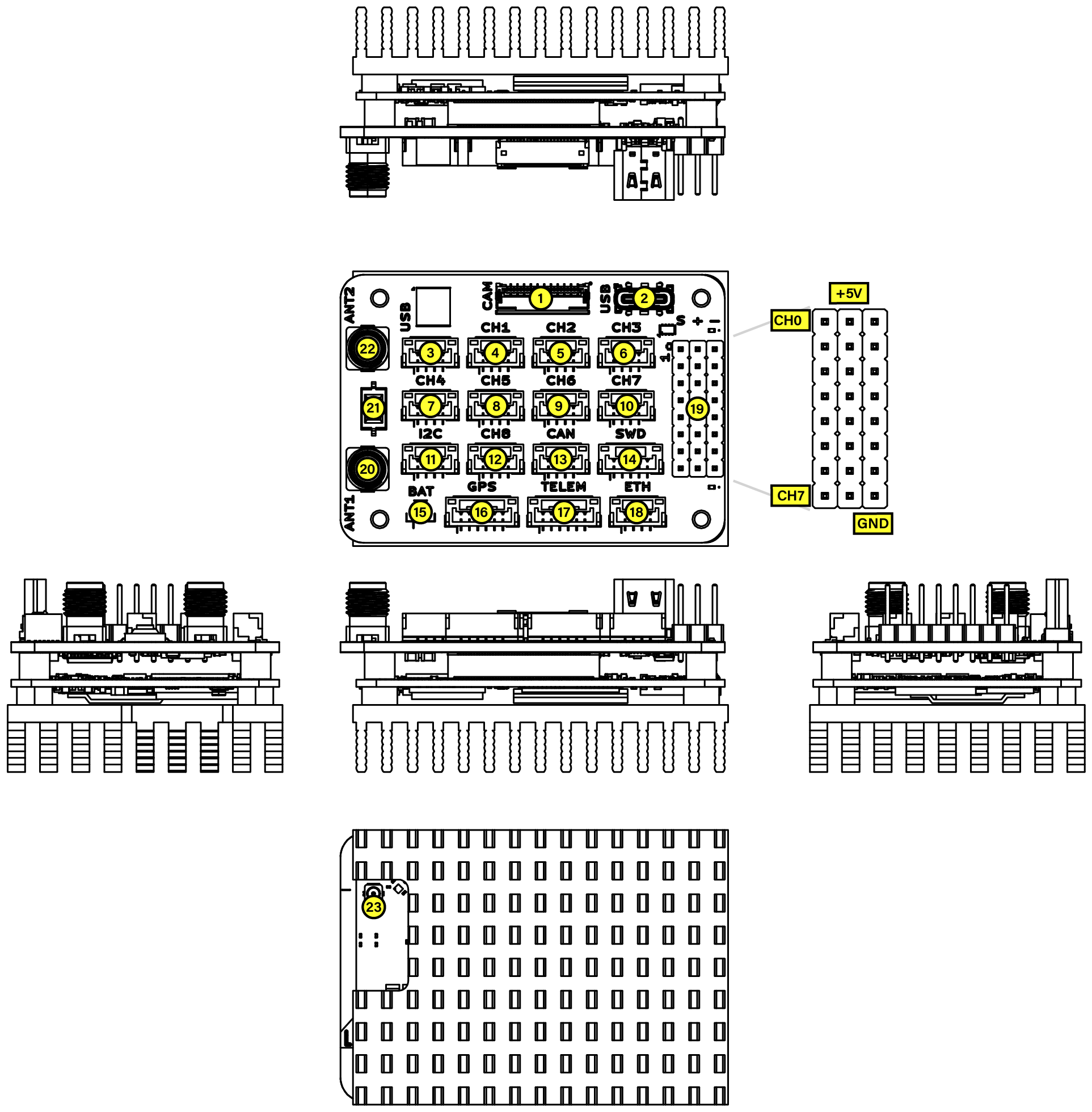
The LightForce Nano PCBA features a highly integrated interface architecture designed to balance high-speed data throughput with versatile peripheral control. The layout is organized into functional zones, supporting a wide array of industrial protocols including Ethernet, CAN bus, and I2C, alongside dedicated headers for Servo and Camera integration.
Furthermore, the board provides 8 primary serial channels (CH1–CH8) and 8 MCU-direct PWM ports, offering extensive flexibility for sensor arrays and custom logic interfacing. This streamlined distribution of interfaces ensures minimal signal interference while facilitating clean cable management within complex system integrations.
Interfaces
| Label No. | Signal | Type | Description |
|---|---|---|---|
| 1 | CAM | Hirose FH12-22S-0.5SH | RPi camera connector |
| 2 | PROG | USB-C | Host connection |
| 3 | USB | JST GH BM04B | USB peripheral connector |
| 4 | CH1 | JST GH BM04B | RS485 (ttyCH1) connector |
| 5 | CH2 | JST GH BM04B | UART (ttyCH2) connector |
| 6 | CH3 | JST GH BM04B | UART (ttyCH3) connector |
| 7 | CH4 | JST GH BM04B | RS485 (ttyCH4) connector |
| 8 | CH5 | JST GH BM04B | RS485 (ttyCH5) connector |
| 9 | CH6 | JST GH BM04B | UART (ttyCH6) connector |
| 10 | CH7 | JST GH BM04B | UART (ttyCH7) connector |
| 11 | I2C | JST GH BM04B | I2C connector |
| 12 | CH8 | JST GH BM04B | RS485 (ttyCH8) connector |
| 13 | CAN | JST GH BM04B | CAN connector |
| 14 | SWD | JST GH BM05B | MCU debug connector |
| 15 | BAT | JST SH BM02B | RTC backup battery |
| 16 | GPS | JST GH BM06B | GPS receiver connector |
| 17 | TELEM | JST GH BM06B | Telemetry radio connector |
| 18 | ETH | JST GH BM04B | Ethernet connector |
| 19 | SERVO | 2.54" Pin Header | 8 channel standard PWM |
| 20 | ANT1 | SMA | Primary antenna (for position) |
| 21 | BOOT | Switch | Bootloader enable switch |
| 22 | ANT2 | SMA | Secondary antenna (for heading) |
| 23 | REMOTE_ID | UF.L | 2.4GHz antenna |
Pinout
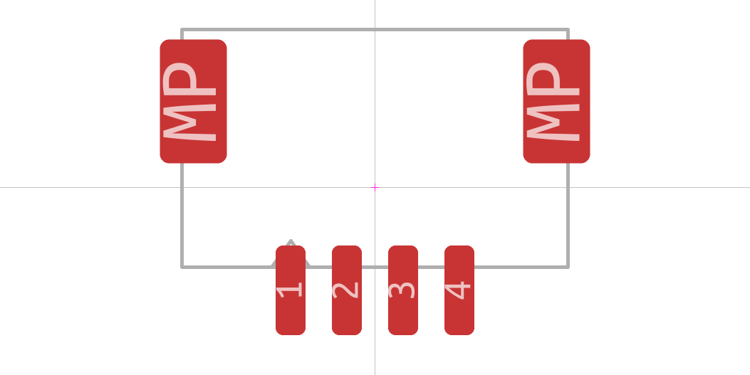
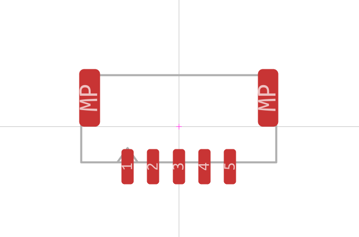
The LightForce Nano unit uses industry-standard Molex Click-Mate 1.5mm pitch connectors for most external interfaces. These connectors provide reliable, tool-free mating and unmating capabilities, ensuring secure connections during operation while maintaining ease of maintenance and field reconfiguration.
USB Connector
| Pin | Signal | Type | Description |
|---|---|---|---|
| 1 | 5V | Power | 5V supply for logic and peripherals (3A total) |
| 2 | DM | I/O | USB 2.0 negative differential pair |
| 3 | DP | I/O | USB 2.0 positive differential pair |
| 4 | GND | Ground | Ground (-) |
RS485 Connector
| Pin | Signal | Type | Description |
|---|---|---|---|
| 1 | GND | Ground | Ground (-) |
| 2 | VBUS | Power (5V-32V) | Input supply voltage |
| 3 | A | I/O | RS485 A signal |
| 4 | B | I/O | RS485 B signal |
UART Connector
| Pin | Signal | Type | Description |
|---|---|---|---|
| 1 | GND | Ground | Ground (-) |
| 2 | VBUS | Power (5V-32V) | Input supply voltage |
| 3 | TX | Output (3.3V) | UART transmit signal |
| 4 | RX | Input (3.3V) | UART receive signal |
I2C Connector
| Pin | Signal | Type | Description |
|---|---|---|---|
| 1 | GND | Ground | Ground (-) |
| 2 | 5V | Power | 5V supply for logic and peripherals (3A total) |
| 3 | SCL | I/O (3.3V, pull-up) | I2C clock signal |
| 4 | SDA | I/O (3.3V, pull-up) | I2C data signal |
CAN Connector
| Pin | Signal | Type | Description |
|---|---|---|---|
| 1 | VBUS | Power (5V-32V) | Input supply voltage |
| 2 | CAN_H | I/O (5V) | CAN high signal |
| 3 | CAN_L | I/O (5V) | CAN low signal |
| 4 | GND | Ground | Ground (-) |
SWD Connector
| Pin | Signal | Type | Description |
|---|---|---|---|
| 1 | GND | Ground | Ground (-) |
| 2 | 3V3 | Power (3.3V) | 3.3V logic supply (2A total) |
| 3 | SWCLK | I/O (3.3V) | Microcontroller SWD clock signal |
| 4 | SWDIO | I/O (3.3V) | Microcontroller SWD data signal |
| 5 | RST | Input (3.3V) | Microcontroller reset signal |
GPS Connector
| Pin | Signal | Type | Description |
|---|---|---|---|
| 1 | 5V | Power | 5V supply for logic and peripherals (3A total) |
| 2 | TX | Output (3.3V) | UART transmit signal |
| 3 | RX | Input (3.3V) | UART receive signal |
| 4 | SCL | I/O (3.3V, pull-up) | I2C clock signal |
| 5 | SDA | I/O (3.3V, pull-up) | I2C data signal |
| 6 | GND | Ground | Ground (-) |
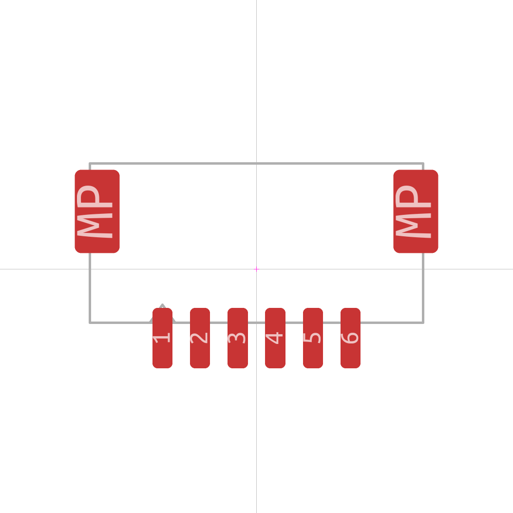
Telemetry Connector
| Pin | Signal | Type | Description |
|---|---|---|---|
| 1 | 5V | Power | 5V supply for logic and peripherals (3A total) |
| 2 | TX | Output (3.3V) | UART transmit signal |
| 3 | RX | Input (3.3V) | UART receive signal |
| 4 | GPIO | I/O (3.3V) | GPIO signal (PPS by default) |
| 4 | GPIO | I/O (3.3V) | GPIO signal |
| 6 | GND | Ground | Ground (-) |
Ethernet Connector
| Pin | Signal | Type | Description |
|---|---|---|---|
| 1 | TR0+ | I/O | |
| 2 | TR0- | I/O | |
| 3 | TR1+ | I/O | |
| 4 | TR1- | I/O |
Harnesses
To maintain the high-reliability standards of the LightForce ecosystem, the selection and construction of wiring harnesses are as critical as the autopilot hardware itself. This section details the connector pinouts and recommended wiring standards required to interface with the unit’s power, telemetry, and high-voltage output domains. Given the high total current capacity and the use of raw battery voltage on the primary output channels, it is imperative to use correctly gauged high-flexibility silicone wire and locking connectors to mitigate the risks of voltage drop, EMI, and mechanical disconnection during high-vibration operation profiles.
Always turn off the unit before connecting or disconnecting a harness.
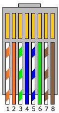
Ethernet
| Pin (Molex Click-Mate) | Pin (RJ45) | Color | Signal | Wire Guage | Description |
|---|---|---|---|---|---|
| 1 | 1 | White-Orange | TR0+ | 24 | |
| 2 | 2 | Orange | TR0- | 24 | |
| 3 | 3 | White-Green | TR1+ | 24 | |
| 4 | 6 | Green | TR1+ | 24 | |
| 5 | White-Blue | TR2+ | 24 | ||
| 4 | Blue | TR2+ | 24 | ||
| 7 | White-Brown | TR3+ | 24 | ||
| 8 | Brown | TR3+ | 24 |
Sensors
The LightForce Nano integrates a high-fidelity sensing array designed to maintain state estimation in the most demanding flight environments. Navigation is anchored by a triple-band, multi-constellation GNSS receiver capable of centimeter-level RTK precision and dual-antenna heading, providing a robust alternative to traditional magnetometers in high-interference scenarios. Complementing this is the industrial-grade IMU, which utilizes an ultra-low-noise gyroscope and accelerometer architecture. This combination ensures that the autopilot maintains superior vibration rejection and orientation stability, even during high-G maneuvers or in proximity to high-current power distribution systems.
Accelerometer Specifications
| Specification | Value | Unit |
|---|---|---|
| Range | 8 | g |
| Resolution | 16 | bits |
| Sensitivity | 4096 | LSB/g |
| Output Data Rate | 800 | Hz |
| Noise Density | 70 | µg/√Hz |
| Shock Tolerance | 20000 | g |
Gyroscope Specifications
| Specification | Value | Unit |
|---|---|---|
| Range | 500 | º/s |
| Resolution | 16 | bits |
| Sensitivity | 65.5 | LSB/(º/s) |
| Output Data Rate | 800 | Hz |
| Noise Density | 0.0038 | º/s/√Hz |
| Shock Tolerance | 20000 | g |
Magnetometer Specifications
| Specification | Value | Unit |
|---|---|---|
| Range | 2000 | uT |
| Resolution | 0.1 | uT |
| Sensitivity | 200 | nT/(º) |
| Output Data Rate | 200 | Hz |
| Shock Tolerance | 20000 | g |
GNSS Specifications
| Specification | Value | Unit |
|---|---|---|
| Position Accuracy | 1.5 (standalone), 0.01 (RTK) | m |
| Velocity Accuracy | 0.05 | m/s |
| Heading Accuracy | 0.13 (1m baseline) | º |
| Time to First Fix | 1 (hot), 28 (warm), 29 (cold) | s |
| Time to RTK convergence | 10 | s |
| Time to Reacquisition | 1 | s |
| Output Data Rate | 20 | Hz |
| Altitude Limit | <80000 | m |
| Velocity Limit | <515 | m/s |
Maintenance
To ensure the long-term operation of the LightForce Nano, a few things should be considered. Given the high-vibration environment typical of UAV/UGV/USV/robotics operations, periodic physical and electrical inspections are vital to prevent fatigue-related failures.
- Connection Integrity: Inspect the Servo and the JST connectors for signs of carbon arcing, thermal discoloration, or loose pins.
- Mounting Security: Verify that all mounting standoffs or vibration isolation grommets remain pliable and secure.
- Cleaning: Remove dust or debris from the unit using low-pressure compressed air. In marine or high-humidity environments, inspect for galvanic corrosion on exposed logic pins.
- Version Parity: Ensure the unit is running the latest stable firmware revision. Check the Support Portal quarterly for critical patches and performance optimizations specifically tuned for your hardware revision.
Hardware Changelog
This section outlines the evolution of the LightForce OEM hardware. Users can identify their hardware version by the serial number on the sticker on the PCB.
| Revision | Serial Number Range | Status | Key Changes |
|---|---|---|---|
| v1.0 | TBD | Deprecated | Initial production release |
| v2.0 | TBD | Current | Fixes to known issues in v1.0, added USB-C PD support |
v1.0
Hardware Changes
Not applicable.
Known Issues
- Magnetometer is inaccessible.
v2.0
Hardware Changes
- Fixed all known issues with v1.0
- Add support for powering up the Nano using the USB-C connector.
Known Issues
None.
Troubleshooting
This section provides diagnostic procedures to identify and resolve common hardware-related issues. The LightForce system is designed with multiple layers of protection; understanding these behaviors is key to distinguishing between a safety feature (like a protective power-cut) and a hardware fault.
Power & Boot Diagnostics
If the unit fails to power on or communicate, follow these diagnostic steps to isolate the cause.
| Symptom | Potential Cause | Action |
|---|---|---|
| Unit fails to boot | Input voltage too low or polarity reversed |
|
| Unit fails to boot (USB-C) | USB-C power delivery |
|
| Unexpected reboots | Power supply voltage too low or cannot supply sufficient current |
|
GNSS Troubleshooting
| Symptom | Potential Cause | Action |
|---|---|---|
| Unable to achieve an RTK Fixed solution | Low-quality antenna or poor sky visibility |
|
| Inaccurate GPS heading | Insufficient separation between GNSS antennas | Increase physical separation between GNSS antennas |